Typical networking and design cases of video surveillance systems using PON technology
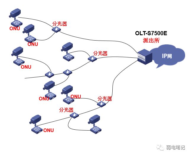
1. Video surveillance solutions for police stations and communities
Demand analysis: 20 - 30 images per police station, up to 100 images, 1 - 2 images per monitoring point, and 5 - 8 images per convergence point; 4 - 8 images are uploaded from branch offices;
Optical fiber resources: Rent optical fiber resources and lay both yourself;
Implementation plan: Place a video codec and ONU on the front end of the camera, transmit it to the OLT switch of Bai-link in the police station through the passive optical network, directly perform soft scheduling through the IP network and related video monitoring software, and fully IP the monitoring network;

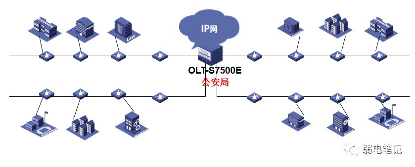
2. Emergency linkage resource integration video surveillance solution (image resource integration):
Demand analysis: Extend the main street and integrate the image resources of hundreds of thousands of cameras in communities, banks, shopping malls, hotels, campuses, enterprises and institutions on both sides of the street into the public security surveillance network, with high image density;
Optical fiber resources: Rent optical fiber resources and lay both yourself;
Implementation plan: Through passive optical networks and chain networking, all unit image resources along the main streets will be IP transmitted;

3. Light path design, power unit
dB is the unit of power gain and is a relative value, dB = 10logX
When calculating how many dB the power of A is greater or less than B, it can be calculated according to Equation 10lgA/B.
For example: A power is twice as large as B power, then 10lgA/B = 10lg2 = 3dB.
dBm is a unit representing the absolute value of power, and dBm is defined as miliwatt.
0dBm= 10 log1 mw; the calculation formula is: 10lg power value/1mW.
For example: if the transmit power is 1mW, the value after conversion in dBm units should be 10lg 1mW/1mW = 0dBm
For a power of 40W, 10lg(40W/1mW)=46dBm
When one dBm is subtracted by another dBm, the result is dB.
For example: 30dBm- 0dBm = 30dB.
In general projects, there is only addition and subtraction between dB and dB, but no multiplication and division.
4. Light path design principles
EPON optical networks must use single-mode optical fibers that comply with the G.652 standard from the OLT equipment end to the ONU equipment end. Optical fibers that meet the G.652 standard can meet the above requirements.
EPON equipment supports two maximum transmission distance specifications of 10KM and 20KM. The 20KM specification requires the use of an OLT board that supports the 20KM transmission specification and an ONU.
The above is the theoretical specification of the maximum transmission distance. The actual maximum transmission distance is based on the total optical path loss, not the distance length.
For example: a 20-kilometer module can transmit a longer distance when only connected to a 1:16 optical splitter; if the optical path loss of a 5KM optical fiber exceeds 30dB, the maximum transmission distance will definitely be less than 5KM;
There is only one most important principle for whether EPON optical paths are qualified and whether they meet transmission:
After the actual project, the optical power on the receiving side of all ONUs is between-8dBm and-24dBm.
According to this rule, refine a few points of attention:
1. Generally, the optical fiber cannot be directly connected to the ONU. An optical splitter or attenuator needs to be added to prevent the light intensity received by the ONU from exceeding the saturated optical power received by the ONU by-3dBm;
2. The optical power in the place where the optical attenuation is greatest cannot be less than-23dBm, otherwise the optical power will be less than the receiving sensitivity of the ONU, and the OLT will not be able to discover the ONU. Note that these places are not necessarily the farthest places, but the incomplete light attenuation is related to distance.
3. The acceptance of light road projects is very critical and it is strongly recommended to do it. Ensure compliance with our rules, because actual projects are often irregular and will cause excessive optical path loss;
4. Before the actual acceptance, you can first predict whether the networking is correct based on the following theoretical calculations!
Note: -24dBm is not the ONU receiving sensitivity. This value is greater than the sensitivity, taking into account the redundancy of 1 to-2dBm;-8dBm is considering that the difference in optical attenuation values between ONUs should not be too large, and the optical power of each ONU should be distributed evenly as much as possible. Therefore, it is recommended to use 50:50 and 25:75 optical splitters for the penultimate and second-level optical splitters.
Theoretical calculation formula for optical path loss:
ONU receiving side optical power =OLT transmitting optical power-optical path loss
Optical path loss = sum of insertion loss values of all optical splitters + fiber length (KM)*0.4+ number of fiber melting points *0.1+ number of flanges *0.2
5. Give two examples
1、

The optical attenuation value of the optical splitter has taken insertion loss into account. It is assumed that each ONU uses a flange connector to access it.
ONU1 optical path attenuation: 15+4.5*0.4+1*0.2=17db
ONU2 optical path attenuation: 0.6+8*0.4+15+1*0.2=19db
ONU3 optical path attenuation: 0.6+8*0.4+15+0.5+6*0.4+1*0.2=22.1db
ONU4 optical path attenuation: 0.6*2+15+(8+3)*0.4+1*0.2=20.8db
ONU5 optical path attenuation: 0.6*3+3.8+(8+3+5)*0.4+1*0.2=12.2db
ONU6 optical path attenuation: 0.6*3+3.8+(8+3+5+9)*0.4+1*0.2=15.4db
The luminous power of 20KMOLT is between 2 and 7dBm, minus the optical path attenuation, which can ensure that all ONUs can go online normally.
The above optical network design has been theoretically calculated OK!
2、

The optical attenuation value of the optical splitter has taken insertion loss into account. It is assumed that each ONU uses a flange connector to access it.
ONU5 optical path attenuation: 0.6*3+15+(8+3+5)*0.4+1*0.2=24db
ONU6 optical path attenuation: 0.6*4+7.2+(8+3+5+6)*0.4+1*0.2=18.6db
ONU7 optical path attenuation:0.6*4+1.9+7.2+(8+3+5+6+3)*0.4+1*0.2=21.7db
A optical path attenuation:0.6*4+1.9*2+(8+3+5+6+3)*0.4+1*0.2=16.4db
ONU8,9 optical path attenuation: 22.2db
The luminous power of 20KMOLT is between 2 and 7dBm, minus the optical path attenuation, which can ensure that all ONUs can go online normally.
The above optical network design has been theoretically calculated OK.
The maximum number of consecutive stages is related to the actual distance and the optical splitter. If the distance is short, the number of consecutive stages can be higher.


